MYSHOP
최근 본 상품


| 상품명 | Pololu High-Power Motor Driver 24v20 |
|---|---|
| 판매가 | 80,364원 |
| 적립금 | 800원 (1%) |
| 상품코드 | P000EBWJ |
| 수량 |   |
| 세액 | 8,036원 |
| 공급사 | Pololu |
| SNS 상품홍보 |
|---|

 |
(최소주문수량 1개 이상 / 최대주문수량 0개 이하)
사이즈 가이드 수량을 선택해주세요.
위 옵션선택 박스를 선택하시면 아래에 상품이 추가됩니다.
| 상품명 | 상품수 | 가격 |
|---|---|---|
| Pololu High-Power Motor Driver 24v20 |   |
( |
총 상품금액(수량) : 0 (0개)

|
||
 |
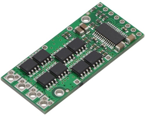
The Pololu high-power motor driver is a discrete MOSFET H-bridge designed to drive large DC brushed motors. The H-bridge is made up of two N-channel MOSFET per leg, and most of the board’s performance is determined by these MOSFETs (the rest of the board contains the circuitry to take user inputs and control the MOSFETs). The MOSFET datasheet is available under the “Resources” tab. The MOSFETs have an absolute maximum voltage rating of 40 V, and higher voltages can permanently destroy the motor driver. Under normal operating conditions, ripple voltage on the supply line can raise the maximum voltage to more than the average or intended voltage, so a safe maximum voltage is approximately 34 V.
Note: Charged battery voltages can be much higher than nominal voltages, so the maximum nominal battery voltage we recommend is 28 V unless appropriate measures are taken to limit the peak voltage.
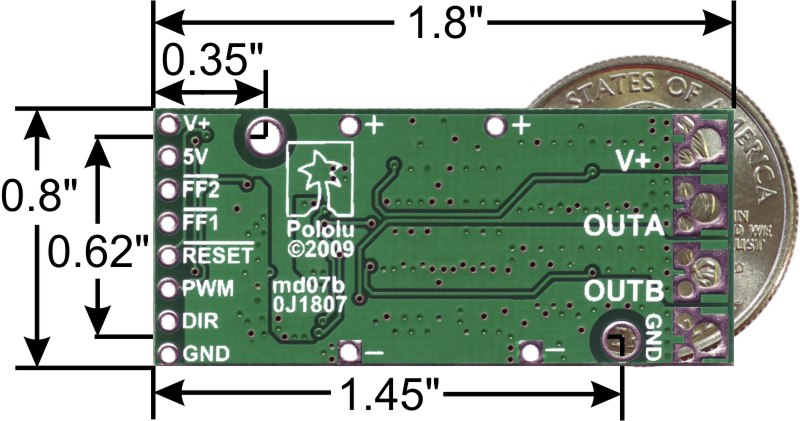
The versatility of this driver makes it suitable for a large range of currents and voltages: it can deliver up to 20 A of continuous current with a board size of only 1.8" by 0.8" and no required heat sink. With the addition of a heat sink, it can drive a motor with up to about 28 A of continuous current. The module offers a simple interface that requires as little as two I/O lines while allowing for both sign-magnitude and locked-antiphase operation. Integrated detection of various short-circuit conditions protects against common causes of catastrophic failure; however, please note that the board does not include reverse power protection or any over-current or over-temperature protection.
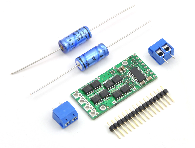
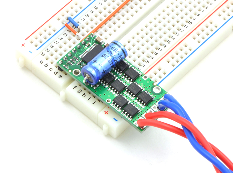
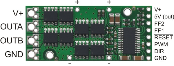
The motor and motor power connections are on one side of the board, and the control connections (5V logic) are on the other side. The motor supply should be capable of supplying high current, and a large capacitor should be installed close to the motor driver. The included axial capacitors can be installed directly on the board in the pins labeled '+' and '-' as shown below. Such installations are compact but might limit heat sinking options; also, depending on the power supply quality and motor characteristics, a larger capacitor might be required. There are two options for connecting to the high-power signals (V+, OUTA, OUTB, GND): large holes on 0.2" centers, which are compatible with the included terminal blocks, and pairs of 0.1"-spaced holes that can be used with perfboards, breadboards, and 0.1" connectors.
Warning: Take proper safety precautions when using high-power electronics. Make sure you know what you are doing when using high voltages or currents! During normal operation, this product can get hot enough to burn you. Take care when handling this product or other components connected to it.
The logic connections are designed to interface with 5V systems (5.5 V max); the minimum high input signal threshold is 3.5 V, so we do not recommend connecting this device directly to a 3.3 V controller. In a typical configuration, only PWM and DIR are required. The two fault flag pins (FF1 and FF2) can be monitored to detect problems (see the Fault Flag Table below for more details). The RESET pin is pulled up to V+ through a 20 kΩ resistor. When held low, it puts the driver into a low-power sleep mode and clears any latched fault flags. The V+ pin on the logic side of the board gives you access to monitor the motor’s power supply (it should not be used for high current). The board also provides a regulated 5 V pin which can provide a few milliamps (this is typically insufficient for a whole control circuit but can be useful as a reference or for very low-power microcontrollers).
 |
| PIN | Default State | Description |
|---|---|---|
| V+ | This is the main 5.5 – 40 V (absolute max) motor power supply connection, which should typically be made to the larger V+ pad. The smaller V+ pads along the long side of the board are intended for power supply capacitors, and the smaller V+ pad on the logic side of the board gives you access to monitor the motor’s power supply (it should not be used for high current). | |
| 5V (out) | This regulated 5V output provides a few milliamps. This output should not be connected to other external power supply lines. Be careful not to accidentally short this pin to the neighboring V+ pin while power is being supplied as doing so will instantly destroy the board! | |
| GND | Ground connection for logic and motor power supplies. | |
| OUTA | A motor output pin. | |
| OUTB | B motor output pin. | |
| PWM | LOW | Pulse width modulation input: a PWM signal on this pin corresponds to a PWM output on the motor outputs. |
| DIR | FLOAT | Direction input: when DIR is high current will flow from OUTA to OUTB, when it is low current will flow from OUTB to OUTA. |
| RESET | HIGH | The RESET pin is pulled up to V+ through a 20 kΩ resistor. When held low, it puts the driver into a low-power sleep mode and clears any latched fault flags. |
| FF1 | LOW | Fault flag 1 indicator: FF1 goes high when certain faults have occurred. See table below for details. |
| FF2 | LOW | Fault flag 2 indicator: FF2 goes high when certain faults have occurred. See table below for details. |
A 16-pin straight breakaway male header, two 100 uF capacitors, and two 2-pin 5mm terminal blocks are included with each motor driver. (Note: The terminals blocks are only rated for 15 A; for higher power applications, use thick wires soldered directly to the board.) Connecting large capacitors across the power supply is recommended; one way to do it is between the '+' and '-' holes, as shown below. The two mounting holes are intended to be used with #2 screws (not included).
|
|
With the PWM pin held low, both motor outputs will be held low (a brake operation). With PWM high, the motor outputs will be driven according to the DIR input. This allows two modes of operation: sign-magnitude, in which the PWM duty cycle controls the speed of the motor and DIR controls the direction, and locked-antiphase, in which a pulse-width-modulated signal is applied to the DIR pin with PWM held high.
In locked-antiphase operation, a low duty cycle drives the motor in one direction, and a high duty cycle drives the motor in the other direction; a 50% duty cycle turns the motor off. A successful locked-antiphase implementation depends on the motor inductance and switching frequency smoothing out the current (e.g. making the current zero in the 50% duty cycle case), so a high PWM frequency might be required.
| Motor Driver Truth Table | ||||
|---|---|---|---|---|
| PWM | DIR | OUTA | OUTB | Operation |
| H | L | L | H | Forward |
| H | H | H | L | Backward |
| L | X | L | L | Brake |
The motor driver supports PWM frequencies as high as 40 kHz, though higher frequencies result in higher switching losses in the motor driver. Also, the driver has a dead time (when the outputs are not driven) of approximately 3 us per cycle, so high duty cycles become unavailable at high frequencies. For example, at 40 kHz, the period is 25 us; if 3 us of that is taken up by the dead time, the maximum available duty cycle is 22/25, or 88%. (100% is always available, so gradually ramping the PWM input from 0 to 100% will result in the output ramping from 0 to 88%, staying at 88% for inputs of 88% through 99%, and then switching to 100%.)
The motor driver can tolerate peak currents in excess of 200 A. The peak current ratings are for quick transients (e.g. when a motor is first turned on), and the continuous rating of 25 A is dependent on various conditions, such as the ambient temperature. The main limitation comes from heating and power dissipation; therefore, at high currents, the motor driver will be extremely hot, and performance can be improved by adding heat sinks or otherwise cooling the board. The driver’s printed circuit board is designed to draw heat out of the MOSFETs, but performance can be improved by adding a heat sink. With a proper heat sink, the motor driver can deliver up to 28 A of continuous current. For more information on power dissipation see the data sheet for the MOSFETs on the Resources tab.
Because there is no internal temperature limiting on the motor driver, the entire system should be designed to keep the load current below the 20 A limit. An easy way to achieve this is to select a motor with a stall current below that limit. However, because a good motor can have stall currents dozens of times higher than the typical operating current, motors with stall currents that are hundreds of amps can be used with this driver as long as the running current is kept low. For example, a motor with a 80 A stall current might run well at 8 A, leaving a safe margin for the current to double for several minutes at a time or to triple for several seconds. If the motor does stall completely for a prolonged period, however, the motor or driver are likely to burn out.
Warning: This motor driver has no over-current or over-temperature shut-off. Either condition can cause permanent damage to the motor driver. You might consider using an external current sensor, such as our ACS714 ±30A bidirectional current sensor carrier to monitor your current draw.
The motor driver can detect three different fault states, which are reported on the FF1 and FF2 pins. The detectable faults are short circuits on the output, under-voltage, and over-temperature. A short-circuit fault is latched, meaning the outputs will stay off and the fault flag will stay high, until the board is reset (RESET brought low). The under-voltage fault disables outputs but is not latched. The over-temperature fault provides a weak indication of the board being too hot, but it does not directly indicate the temperature of the MOSFETs, which are usually the first components to overheat. The fault flag operation is summarized below.
| Flag State | Fault Description | Disable Outputs | Latched Until Reset | |
|---|---|---|---|---|
| FF1 | FF2 | |||
| L | L | No fault | No | No |
| L | H | Short Circuit | Yes | Yes |
| H | L | Over Temperature | No | No |
| H | H | Under Voltage | Yes | No |
There are four versions of the G2 high-power motor driver, which all share compatible pinouts. The following table provides a comparison of the G2 drivers:
| Pololu G2 High-Power Motor Drivers | |||
|---|---|---|---|
| Name | Absolute max input voltage | Max nominal battery voltage | Max continuous current |
| G2 High-Power Motor Driver 18v25 | 30 V | 18 V | 25 A |
| G2 High-Power Motor Driver 18v17 | 30 V | 18 V | 17 A |
| G2 High-Power Motor Driver 24v21 | 40 V | 28 V | 21 A |
| G2 High-Power Motor Driver 24v13 | 40 V | 28 V | 13 A |
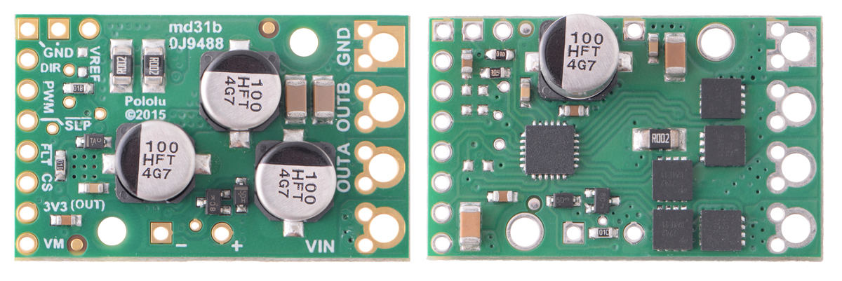 |
Pololu G2 High-Power Motor Driver 24v21 and 24v13. |
|---|
Note: As an alternative to these motor drivers, our Simple Motor Controllers have similar power characteristics and offer high-level interfaces (e.g. USB, RC hobby servo pulses, analog voltages, and TTL serial commands) that make them easier to use for some applications.
There are also nine original high-power motor driver versions. The three CS versions have the same pinout, and the six non-CS versions have the same pinout. The following table provides a comparison of these first-generation drivers:
| Pololu high-power motor drivers | ||
|---|---|---|
| Name | Max nominal battery voltage (V) | Max continuous current (A) w/o heat sink |
| High-power motor driver 18v25 CS | 18 | 25 |
| High-power motor driver 18v25 | 18 | 25 |
| High-power motor driver 18v15 | 18 | 15 |
| High-power motor driver 24v23 CS | 28 | 23 |
| High-power motor driver 24v20 | 28 | 20 |
| High-power motor driver 24v12 | 28 | 12 |
| High-power motor driver 36v20 CS | 36 | 20 |
| High-power motor driver 36v15 | 36 | 15 |
| High-power motor driver 36v9 | 36 | 9 |
* 세금계산서 발행방법은 게시판 공지사항 참조.
* 기술문의는 이메일(master@toolparts.co.kr)로 문의.
전자부품 특성상 제품에 이상이 있거나, 상품정보와 상이한 경우 외 에 단순 고객변심으로는
교환 반품이 불가능 합니다 구매전 이점 유의해 주세요!!!
고액결제의 경우 안전을 위해 카드사에서 확인전화를 드릴 수도 있습니다. 확인과정에서 도난 카드의 사용이나 타인 명의의 주문등 정상적인 주문이 아니라고 판단될 경우 임의로 주문을 보류 또는 취소할 수 있습니다.
무통장 입금은 상품 구매 대금은 PC뱅킹, 인터넷뱅킹, 텔레뱅킹 혹은 가까운 은행에서 직접 입금하시면 됩니다.
주문시 입력한 입금자명과 실제입금자의 성명이 반드시 일치하여야 하며, 7일 이내로 입금을 하셔야 하며 입금되지 않은 주문은 자동취소 됩니다.
교환 및 반품이 가능한 경우
- 상품을 공급 받으신 날로부터 7일이내 단, 가전제품의
경우 포장을 개봉하였거나 포장이 훼손되어 상품가치가 상실된 경우에는 교환/반품이 불가능합니다.
- 공급받으신 상품 및 용역의 내용이 표시.광고 내용과
다르거나 다르게 이행된 경우에는 공급받은 날로부터 3월이내, 그사실을 알게 된 날로부터 30일이내
교환 및 반품이 불가능한 경우
- 고객님의 책임 있는 사유로 상품등이 멸실 또는 훼손된 경우. 단, 상품의 내용을 확인하기 위하여
포장 등을 훼손한 경우는 제외
- 포장을 개봉하였거나 포장이 훼손되어 상품가치가 상실된 경우
(예 : 가전제품, 식품, 음반 등, 단 액정화면이 부착된 노트북, LCD모니터, 디지털 카메라 등의 불량화소에
따른 반품/교환은 제조사 기준에 따릅니다.)
- 고객님의 사용 또는 일부 소비에 의하여 상품의 가치가 현저히 감소한 경우 단, 화장품등의 경우 시용제품을
제공한 경우에 한 합니다.
- 시간의 경과에 의하여 재판매가 곤란할 정도로 상품등의 가치가 현저히 감소한 경우
- 복제가 가능한 상품등의 포장을 훼손한 경우
(자세한 내용은 고객만족센터 1:1 E-MAIL상담을 이용해 주시기 바랍니다.)
※ 고객님의 마음이 바뀌어 교환, 반품을 하실 경우 상품반송 비용은 고객님께서 부담하셔야 합니다.
(색상 교환, 사이즈 교환 등 포함)
상품의 사용후기를 적어주세요.
게시물이 없습니다


상품에 대해 궁금한 점을 해결해 드립니다.
게시물이 없습니다