MYSHOP
최근 본 상품


| 상품명 | ACS709 Current Sensor Carrier -75A to +75A |
|---|---|
| 판매가 | 20,818원 |
| 적립금 | 200원 (1%) |
| 상품코드 | P000EHFJ |
| 수량 |   |
| 세액 | 2,082원 |
| 공급사 | Pololu |
| SNS 상품홍보 |
|---|

 |
(최소주문수량 1개 이상 / 최대주문수량 0개 이하)
사이즈 가이드 수량을 선택해주세요.
위 옵션선택 박스를 선택하시면 아래에 상품이 추가됩니다.
| 상품명 | 상품수 | 가격 |
|---|---|---|
| ACS709 Current Sensor Carrier -75A to +75A |   |
( |
총 상품금액(수량) : 0 (0개)

|
||
 |
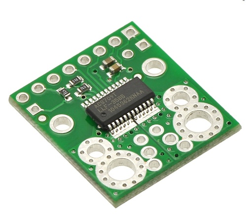
This current sensor is a carrier board or breakout board for Allegro’s ACS709LLFTR-35BB-T Hall effect-based linear current sensor with overcurrent fault output; we therefore recommend careful reading of the ACS709 datasheet (1MB pdf) before using this product. The sensor has an operating voltage of 3 V to 5.5 V and an output sensitivity of 18.5 mV/A when Vcc is 3.3 V (or 28 mV/A when Vcc is 5 V). The following list details some of the sensor’s key features:
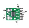
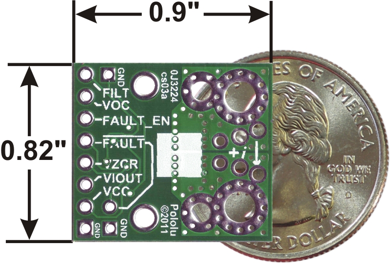
The pads are labeled on the bottom silkscreen, as shown in the picture above. The silkscreen also shows the direction that is interpreted as positive current flow via the +i arrow.
Note: The sensor’s extended -75 A to 75 A range should be limited to transient currents. In our tests, we found that the IC could tolerate 50 A for 20 seconds or 37.5 A for 150 seconds before exceeding its maximum temperature rating of 150°C. Therefore, unless you are taking special steps to keep the IC cool, we recommend limiting continuous currents to under 30 A. Even with a low conductive path resistance of 1.1 mΩ, the board can get hot enough to burn you when the current is in the tens of amps, and the IC does not feature any kind of over-temperature protection, so thermal issues should be taken into consideration for high currents.
 |
The only connections required to use this sensor are the input current (IP+ and IP-), logic power (VCC and GND), and the sensor output (VIOUT). All of the other pins are optional, as are the two external capacitors shown in the diagram to the right.
The sensor requires a supply voltage of 3 V to 5.5 V to be connected across the VCC and GND pads, which are labeled on the bottom silkscreen. The sensor outputs an analog voltage that is linearly proportional to the input current. The quiescent output voltage is VCC/2 and changes by 28 mV per amp of input current (when VCC = 5 V), with positive current increasing the output voltage and negative current decreasing the output voltage. For an arbitrary input current i (in amps), the sensor’s output voltage can be more generally represented as:
VIOUT = (0.028 V/A * i + 2.5 V) * VCC / 5 V
The VZCR pin is the voltage reference output pin and can be used as a zero current (0 A) reference. It will be approximately equal to VCC/2 and lets you more accurately compute the current from the VIOUT output voltage.
The FILT pin lets you adjust the board’s bandwidth by adding a capacitor, CF, to ground (a ground pad has been added next to the FILT pin for convenience). Without any external filter capacitor, the bandwidth is 120 kHz. The datasheet provides more information on how the external filter capacitor affects bandwidth.
The FAULT pin is normally high and latches low when the current exceeds the overcurrent fault switchpoint (Ioc). This switchpoint is set by the voltage applied to the VOC pin and is dependent on the voltage divider shown in the schematic diagram below. By default, Ioc is set to 57 A, but it can be altered by adding external resistors to the voltage divider to change the VOC voltage. Once the FAULT pin is latched low, it can be reset by driving the FAULT_EN input low (this input is pulled high on the board). An external capacitor, COC, can be added to increase the overcurrent fault response time. Without this capacitor, the fault response time is typically under 2 us. For detailed information on using the overcurrent fault feature, including some key restrictions on the overcurrent threshold, please refer to the ACS709 datasheet (1MB pdf).
|
|
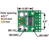
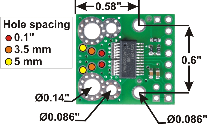
The input current can be connected to the board in a variety of ways. Holes with 0.1″, 3.5 mm, and 5 mm spacing are available as shown in the diagram above for connecting male header pins or terminal blocks. For high-current applications, you can solder wires directly to the through-holes that best match your wires, or you can use solderless ring terminal connectors, as shown in the picture above. The large through-holes are big enough for #6 screws.
Warning: This product is intended for use below 30 V. Working with higher voltages can be extremely dangerous and should only be attempted by qualified individuals with appropriate equipment and protective gear.
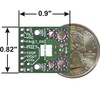
The board has two mounting holes on the logic side of the board. These mounting holes are 0.6" apart and are designed for #2 screws.
This board ships assembled with all surface mount components, and an 8×1 strip of 0.1″ header pins is included but not soldered in, as shown in the picture below.
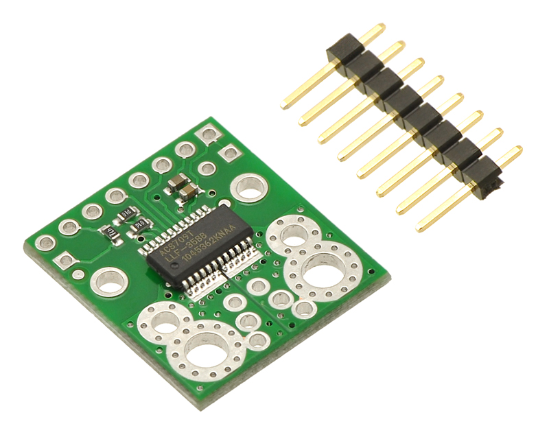 |
ACS709 current sensor carrier with included 8 × 1 0.1″ header pins. |
|---|
 |
ACS709 current sensor carrier schematic diagram. |
|---|
* 세금계산서 발행방법은 게시판 공지사항 참조.
* 기술문의는 이메일(master@toolparts.co.kr)로 문의.
전자부품 특성상 제품에 이상이 있거나, 상품정보와 상이한 경우 외 에 단순 고객변심으로는
교환 반품이 불가능 합니다 구매전 이점 유의해 주세요!!!
고액결제의 경우 안전을 위해 카드사에서 확인전화를 드릴 수도 있습니다. 확인과정에서 도난 카드의 사용이나 타인 명의의 주문등 정상적인 주문이 아니라고 판단될 경우 임의로 주문을 보류 또는 취소할 수 있습니다.
무통장 입금은 상품 구매 대금은 PC뱅킹, 인터넷뱅킹, 텔레뱅킹 혹은 가까운 은행에서 직접 입금하시면 됩니다.
주문시 입력한 입금자명과 실제입금자의 성명이 반드시 일치하여야 하며, 7일 이내로 입금을 하셔야 하며 입금되지 않은 주문은 자동취소 됩니다.
교환 및 반품이 가능한 경우
- 상품을 공급 받으신 날로부터 7일이내 단, 가전제품의
경우 포장을 개봉하였거나 포장이 훼손되어 상품가치가 상실된 경우에는 교환/반품이 불가능합니다.
- 공급받으신 상품 및 용역의 내용이 표시.광고 내용과
다르거나 다르게 이행된 경우에는 공급받은 날로부터 3월이내, 그사실을 알게 된 날로부터 30일이내
교환 및 반품이 불가능한 경우
- 고객님의 책임 있는 사유로 상품등이 멸실 또는 훼손된 경우. 단, 상품의 내용을 확인하기 위하여
포장 등을 훼손한 경우는 제외
- 포장을 개봉하였거나 포장이 훼손되어 상품가치가 상실된 경우
(예 : 가전제품, 식품, 음반 등, 단 액정화면이 부착된 노트북, LCD모니터, 디지털 카메라 등의 불량화소에
따른 반품/교환은 제조사 기준에 따릅니다.)
- 고객님의 사용 또는 일부 소비에 의하여 상품의 가치가 현저히 감소한 경우 단, 화장품등의 경우 시용제품을
제공한 경우에 한 합니다.
- 시간의 경과에 의하여 재판매가 곤란할 정도로 상품등의 가치가 현저히 감소한 경우
- 복제가 가능한 상품등의 포장을 훼손한 경우
(자세한 내용은 고객만족센터 1:1 E-MAIL상담을 이용해 주시기 바랍니다.)
※ 고객님의 마음이 바뀌어 교환, 반품을 하실 경우 상품반송 비용은 고객님께서 부담하셔야 합니다.
(색상 교환, 사이즈 교환 등 포함)
상품의 사용후기를 적어주세요.
게시물이 없습니다


상품에 대해 궁금한 점을 해결해 드립니다.
게시물이 없습니다